Creo 2 0 Sheet Metal Bend

Sheet Metal Design Intent Objects For Sheetmetal Design Ptc Learning Connector

Creo Parametric Sheetmetal Bends Part 1 Youtube

Sheetmetal Flat Pattern Preview Window In Creo Parametric Flats Patterns Pattern Parametric

Twist Command Sheet Metal Creo 2 0 Youtube

Creo Parametric Sheetmetal Punch Forms Tutorial Youtube

Sheet Metal Modeling And Drawing In Creo Youtube

Figure 1 figure 2.
Creo 2 0 sheet metal bend. Edit sheet metal rule and set miter gap to 0 01. It is recommended to complete the following or have the equivalent creo parametric experience. Notice the corner conditions for 2 bend intersection has relief shape option and setting it here will affect all the features created with this rule 2. Open drawing sheet place flatten view.
Without adding a bend the operation convert to sheetmetal does not seem to work unless i have already put a bend in the part. Click the options tab to control the length of the wall when you edit a bend. Ptc was quite proud of it. Now you can use the draggers to change the angle or radius.
5 blend create a sheet metal wall by blending several sections sketched in parallel planes as shown in figure sm 10. This is a simplified version so i can t use forms or punches. Create edge flange override rules 2 bend corner override relief shape arc weld. Start by selecting the bend surface.
Figure sm 12 base feature offset wall. Investigating a sheet metal part. Sorry to jump in here but i have a part that i design in wood. If i had to i would add the tongue after the bend feature.
In the creation. I am wanting to put a bend in to assimilate a bend like in sheetmetal. 2 2 sheet metal conversion 2 2 1 ripping the shell in figure 2 does not yet represent a piece of bent sheet metal as it is not yet obvious which edges are folded and which are not continuous ripped. Selecting a bend editing option.
Click edit bend in the mini toolbar. 0 kudos reply. Geometry is simple it is flat with zero bends. Figure sm 10 base feature blended wall flat sketch the boundaries of the wall fig.
In this tutorial i will create a mounting bracket by utilizing sheet metal capabilities of creo parametric 2 0 first of all base feature will be created usin. In annotate tab select show annotations icon. Figure sm 11 feature flat wall offset create a wall that is offset from a surface fig. The sheet steel used for idp construction is 0 7mm.
Introduction to solid modeling part 1. Now select bend order select the bends one by one if it is difficult to select bend switch to wireframe view. What is the method to create sheet metal bend that has a flat area as shown since bend line in sketch must be one entity. Now that you have a sheet metal part just go to the edit bend command.
I thought they added something for this in creo 3 0. Figure 2 shows the resulting shell.
Allowance Tables And Formulas

Add Flat Pattern In Sheet Metal Drawings Creo Parametric 5 0 Youtube

Solidworks Tutorial Folding And Unfolding Sheet Metal Bends By Solidwize
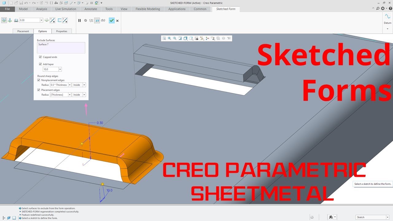
Creo Parametric Sheetmetal Sketched Forms Tutorial Youtube

Creo Parametric Sheetmetal Planar Bends Youtube

V Posledovatelnyh Shtampah Soderzhatsya Neskolko Standartnyh Chastej V Dannom Video Pokazyvaetsya Kak Eti Chasti Mogut Byt Dobavleny V Bazu Ads Progress Library

Pin On Ew

Creo Parametric Sheetmetal Design Boundary Systems Pushing The Limits Of Product Development

Flapping Wing Mechanism1 Mechanical Engineering Mechanic Engineering

Solidworks Sheet Metal Drawing Tutorial Bend Line Flat Pattern Unfolded Bend Table Punch Table Youtube
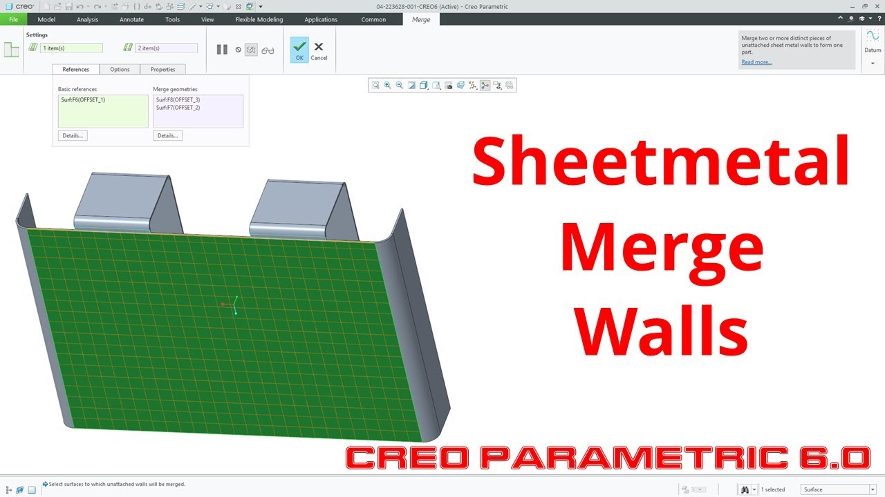
Creo Parametric 6 0 Sheetmetal Merge Walls Youtube

Creo Parametric 6 0 Sheetmetal Flat And Flange Wall Changes Youtube

Precise 2 Unfold Sheet Metal Model In Autocad Sample 3 Youtube

Creo Sheet Metal Unbend With References Deformations Distinct Areas In Creo Parametric Youtube

Flange All Types Command In Creo Sheetmetal Youtube

Complex Sheet Metal Parts Made Easy In Solidworks Youtube

Fillet In Solidworks By Smart Corner بالعربي Solidworks Corner Smart

Intro To Surface Design 2 Solidworks Tutorials Surface Design Solidworks Tutorial Solidworks Tutorial
Https Encrypted Tbn0 Gstatic Com Images Q Tbn 3aand9gcshvsmiewf8zz0llvgus01kk2qa0shi6v Iyk6p6dkf1rva6h9v Usqp Cau

Design And Build An English Wheel English Wheel Metal Furniture Design Sheet Metal Tools

Watch Webcast Replay Sheetmetal Tips And Tricks

My Opinions On Sheetmetal Autodesk Community Community Archive Read Only

Sheet Metal Convert Solid To Sm Autodesk Community

Creo Sheet Metal Project Box Youtube

Software Solutions For The Sheet Metal Industry

New To Creo 4 0 Sheetmetal Design Edge Bend Is Improved In Sheetmetal Design Youtube

Tutorial De Solidworks Superficies 3d Design Surface Solidworks Tutorial Solidworks Autocad Training

Sheet Metal Corner Relief Tools Cad Design Tools Youtube

Pin By Josua Tawake On Oblique Cone Sheet Metal Fabrication Sheet Metal Work Sheet Metal

Assembly And Details Machine Drawing Pdf Mechanical Engineering Design Mechanical Design Technical Drawing

Chassis Drawing Sheet Sheet Metal Drawing Sheet Metal Drawing Sheet

How To Convert Part Model To Sheetmetal In Creo Youtube

Advanced Solidworks 2012 Tutorial Patterning And Positioning Bodies Youtube Solidworks Solidworks Tutorial Tutorial

Announcing Sheet Metal For Bricscad V17 2 Bricsys Cad Blog
Pin On Solidworks

Trumpf 3000 Cnc Punch Press In Action Manufacturing Stainless Steel Sheet Metal Chassis Plates Http Www Vandf Co Uk Plant List Trumpf 3000r

Bend Back Selected Contours In Sheet Metal Creo Parametric I Youtube

Solidworks 2014 Lets You Quickly Calculate Machining Costs For A Part Without Having To Set Up Templates Engenharia Da Computacao Engenharia Computacao Grafica
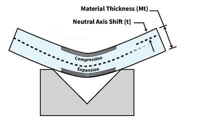
K Factors Y Factors And Press Brake Bending Precision

Whitworth Mechanism Kulisovy Kyvavy Mechanizmus 3d Creo Elements Youtube Mechanical Projects Tool Storage Diy Mechanical Design

How To Add Sheet Metal Gusset In Creo Pro E Users Ptc Creo Grabcad Groups

Solidworks Tutorial For Beginners Exercise 41 Youtube Solidworks Tutorial Workout For Beginners Solidworks

