Describe The Creation Of A Sheet Metal Flange

Sheet Metal Flange Features

My Opinions On Sheetmetal Autodesk Community Community Archive Read Only

Sheet Metal Flange Manilupation Onshape
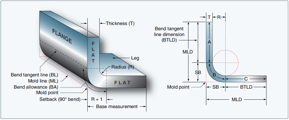
Aircraft Sheet Metal Layout And Forming Aircraft Systems

Flanges Clampco Products

Sheet Metal Design Guide Geomiq
Many other sheet metal cutting operations may occur in a larger progressive process.
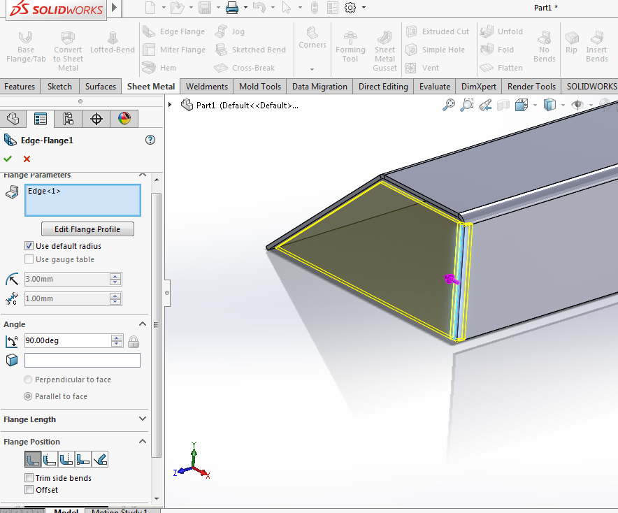
Describe the creation of a sheet metal flange. Create 3 bend corner on flange in sheet metal while creating a flange add a 3 bend corner using auto miter. Create a flange in sheet metal and specify the width of the flange. List and describe the differences between the flange and face commands. You can specify the depth and the angle of the flange and whether it is created inside or outside the existing face.
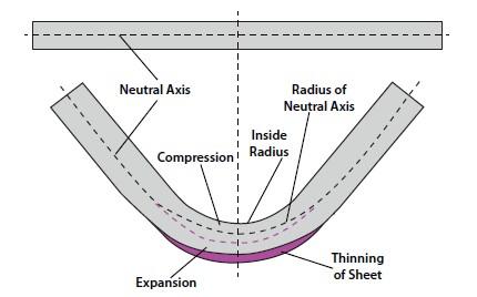
List and describe two of the settings available in the sheet metal defaults in creo parametric. A base flange is the first feature in a new sheet metal part. List and describe two of the factors that can change the k factor value. How is the k factor used to calculate the flattened length in sheet metal flat patterns.
Create flange with from to selections in sheet metal create a flange and define its width with from to selections. Notching as discussed is generally a progressive process in the creation of a profile. Avoid large sheet metal parts with small bent flanges. During the creation of a sheet metal face the face can extend to meet another face and connect it with a bend.
You can also specify the width or offset of the new flange. In the end of this rod a slot is cut the depth of which is the same as the depth of the flange you wish to create. The only tool you need is a length of 1 2 steel rod about 6 or so long. Design for manufacturability sheet metal guidelines bends for the ease of manufacturing multiple bends on the same plane should occur in the same direction.
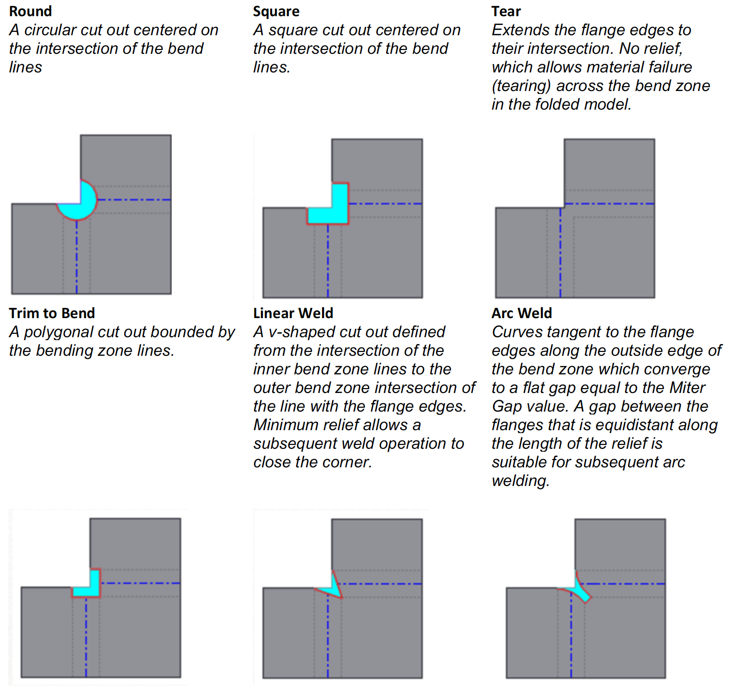
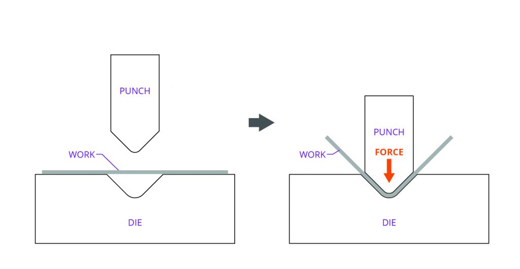
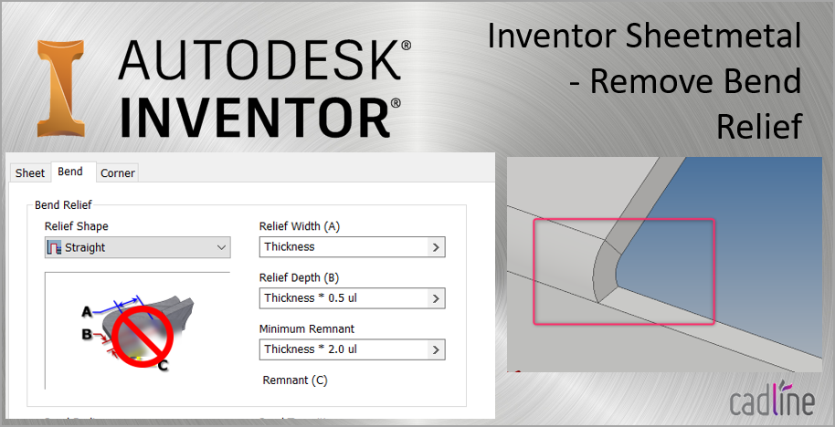
As per sheet metal design thumb rules the depth of bend relief should be greater than or equal to the inside bend radius of the bend and the width of the bend relief should be the same as the sheet metal thickness or more. The flange which does not have relief will result in a greater amount of distortion or tearing of the adjacent material. Flange dialog box defines a flange by adding a sheet metal face and a bend to an edge or edge loop on a face. Forming a sheet metal flange.
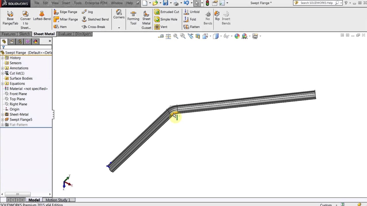
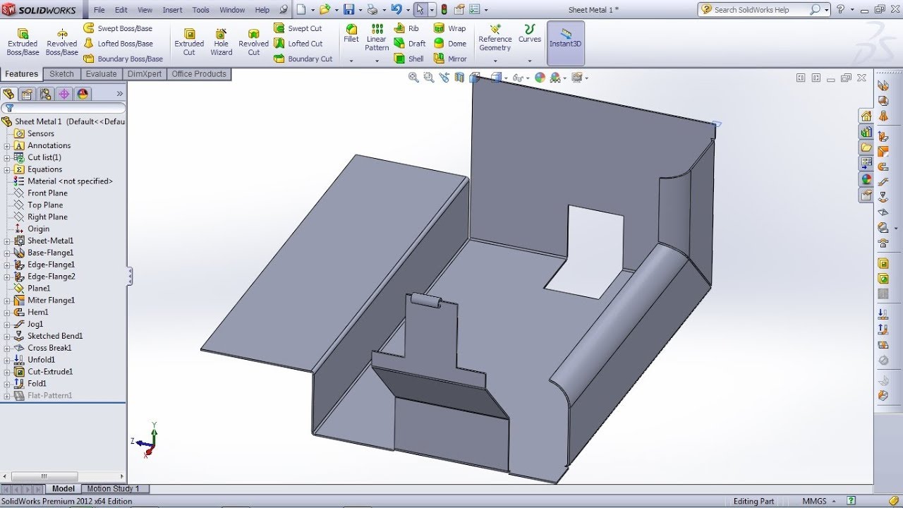
In days gone by when most bodywork was done by skilled tinsmiths with no modern machinery many methods of working existed which have largely been forgotten now this is possibly one of them. Often the order in which the operations occur is important. When you add a base flange feature to a solidworks part the part is marked as a sheet metal part. Use the flange tool on the sheet metal features toolbar to add a sheet metal face and a bend to an existing sheet metal face.
Sheet metal manufacturing is a good example of an industry that uses a large amount of progressive processing. False true or false. In low carbon steel sheet metal the minimum radius of a bend should be one half the material thickness or 0 80 mm. The base flange feature is created from a sketch.
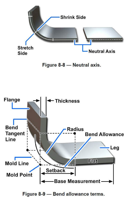
A flange feature consists of a face and bend connected to an existing face along a straight edge. To add a flange feature you select one or more edges and specify the size and position of the material added.
Sheet Metal Success In Solidworks Engineers Rule
Sheet Metal Design Guidelines How To Design Good Sheet Metal Parts

Sheet Metal An Overview Sciencedirect Topics
Sheetmetal Not Able To Make A Box Correctly Please Help Autodesk Community Fusion 360
Creo Sheetmetal Tutorial How To Create Flange Wall Feature Youtube
Solidworks Sheet Metal Tutorial For Beginner 1 Base Flange Tab Edge Flange Miter Flange Hem Youtube
Analyzing The K Factor In Sheet Metal Bending

Solidworks Sheet Metal Gauge Table And Properties Youtube
Sweet Relief How To Avoid Hole Distortion In Sheet Metal Parts
Following Dfm Guidelines For Working With Sheet Metal Machine Design

Nx 11 Advanced Sheet Metal For Automotive And Aerospace Parts Nx Design
Developments And Intersection Drawings Computer Aided Drafting Design

Solidworks Tutorial Using The Jog Feature Lynda Com Youtube

Pin On Art

Solidworks Sheet Metal Tutorial Hopper Youtube Sheet Metal Drawing Sheet Metal Metal Sheet Design

Solidworks Tutorial Sheet Metal Edge Flange Youtube

Sheet Metal Understanding K Factor

Pin On Solidworks
Https Encrypted Tbn0 Gstatic Com Images Q Tbn 3aand9gcq Ezzigvpy99e1izogewhsfm Cw9r37y885aum1imvjg0nsrxh Usqp Cau

Solidworks Sheet Metal Lofted Bend Youtube
Inventor Sheetmetal Remove Flange Bend Relief Cadline Community
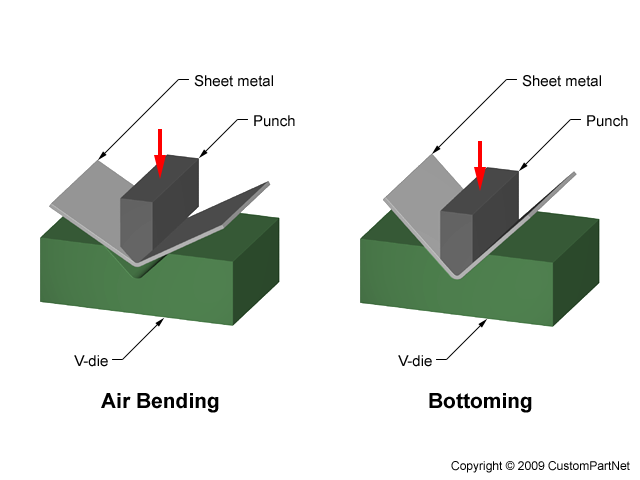
Sheet Metal Forming
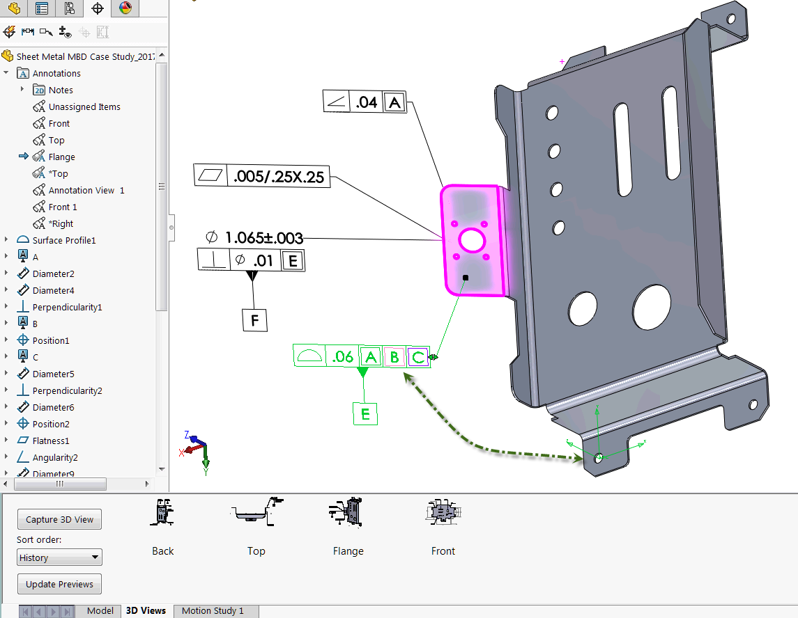
How To Define The Mbd Data Of Sheet Metal Parts Engineers Rule
Solidworks Swept Flanges And Miter Flanges Youtube

Flange Feature In Inventor 2015 Youtube

Shaping A Sheet Metal Edge Flange
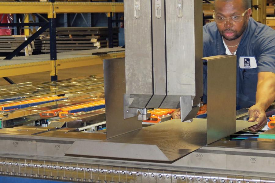
The Sheet Metal Bending Department Evolves

Mechanical Design Tutorial Sheetmetal Design

Design Sheet Metal Parts In Fusion 360 Toglefritz S Lair

Inventor Sheet Metal Cylinder Tutorial With Contour Roll Command Youtube

Pin On Solidworks

Calculate K Factor Bend Allowance And Y Factor For Sheet Metal Bending Gasparini Industries

Inventor Holes In A Sheetmetal Curve Youtube
What To Do When Cutouts And Other Components Need To Be Placed Close To A Bend Protocase Blog

Solidworks Sheet Metal Exercise Basics Youtube Sheet Metal Sheet Metal Drawing Solidworks
Http Www Webpages Uidaho Edu Mindworks Solidworks Topic 20references Sheet 20metal Pdf

Solidworks Sheet Metal Tutorial Panel Youtube Sheet Metal Sheet Metal Drawing Sheet Metal Work

3 Ways To Predict Cracking And Splitting During Sheet Metal Forming Wiley Metal

How Do You Create This Curved Edge Flange In Solidworks Grabcad Questions
Sheet Metal Folding Evolves
K Factor Sheetmetal Me

Sheet Metal Forming Process Chapter 7 Ppt Download

